8+ Free Space Loss
Images. Ieee defines it as the loss between two isotropic radiators in free space, expressed as a power ratio. Both equations are given below
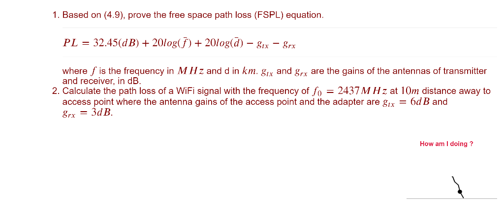
1 Based On 4 9 Prove The Free Space Path Loss Chegg Com from media.cheggcdn.com
Propagate linear fm pulse waveform to target and back. The free space path loss is used to predict the strength of a rf signal at a particular distance. The following table shows the free space path loss at 1 meter (3 feet) away from the transmitter at various frequencies commonly used in the telecommunications industry.
Each time you call step on a phased.freespace object, you specify not only the signal to propagate, but also the location and velocity of the signal origin and destination.
The free space path loss can be expressed in terms of either the wavelength or the frequency. The free space loss can be calculated by the formula listed below which is the transmission loss between two antennas, separated by a distance. For more accuracy path loss (pl) calculation you can add transmitting (receiving) antenna. The free space propagation model assumes a transmit antenna and a receive antenna to be located in an otherwise empty environment.